


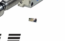
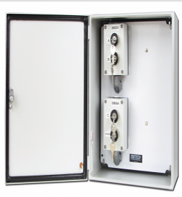
Series 4600
Lever Switch
Lever Switch
Railroad Control Equipment
HOME |
CONTROL PANELS |
SWITCHES |
CONTROL UNITS


Home
Products

Contact Us

Contact Us
Home
Home
Home
Products
Products
Projects
Projects
Projects
Contact Us
Products
Projects
Contact Us
SUPPORT EQUIPMENT |
CUSTOM SPECIAL PARTS |
CONTACT ENTECH

General Characteristics of Multiple Contact Switches
The following information has been provided to help familiarize our customers with some of the common terminology used describing switch functions, contact forms, ectera. Click any of the following terms to learn more.
Contact Forms
Contacts
Blades
Insulators
Contact Forms
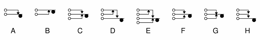
Entech Controls Corporation uses the eight basic standard contact arrangements. These are designated "Form A" through "Form H", as shown in the figure below. The black dot represents a lever that pushes up or down on the blade mechanism. Each blade is physically separated by an insulator to keep it from contacting the other blades until it is activated.
The following information has been provided to help familiarize our customers with some of the common terminology used describing switch functions, contact forms, ectera. Click any of the following terms to learn more.
Contact Forms
Contacts
Blades
Insulators
Contact Forms
Entech Controls Corporation uses the eight basic standard contact arrangements. These are designated "Form A" through "Form H", as shown in the figure below. The black dot represents a lever that pushes up or down on the blade mechanism. Each blade is physically separated by an insulator to keep it from contacting the other blades until it is activated.
Pileups
Lever Function
Lever Design
Lever Function
Lever Design
Railroad Control Equipment
Custom Switches
Ground Detector Equipment


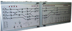

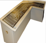
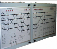
Control Consoles/Panels


Controller Switches
Rack Mounted Panels
Form A
This contact structure consists of two blades that are not physically touching each other. This switch type is designated a "NORMALLY OPEN" contact because the blades are not touching one another when the lever is not activated. Moving the lever up (which is done mechanically in the switch) pushes the lower blade upward until it contacts the upper blade. Moving the lever back down will separate the two blades. When the blades are touching, the electrical circuit is "on". If they are not touching, the electrical circuit is "off".
Form B
This form also consits of two blades, constructed like "Form A" except the blades are touching each other before the lever has been moved. Since the electrical circuit is "on", moving the lever mechanically upwards causes the blades to open and turn the circuit "off". The designation is "NORMALLY CLOSED".
Form C
This form consists of three blades that combine the functions of both "Form A" and "Form B" type switches. The center blade is common to both "Form A" and "Form B" electrical circuits. Pushing the lever upward opens the lower blade (Form B) and closes the common blade with the upper blade (Form A).
Form D
Pushing the lever upward causes the bottom blade to meet with the top blade before the middle blade opens. Thus, it is designated as a "MAKE BEFORE BREAK" type switching function.
Form E
Pushing the lever upward causes the bottom blade to open first, meet the top blade second, and open the middle blade last. Therefore, this form is designated as a "BREAK BEFORE MAKE BEFORE BREAK".
Form F
This form has all blades "NORMALLY OPEN". The lever action is to both push and pull the center (common) blade. Pushing upward causes the common and upper blades to meet, while pushing downward causes the common blade to meet with the lower blade.
Form G
This form is the opposite of "Form F". By pushing the lever upwards, the contact between the middle and lower blade is broken. Pushing the lever downward will break the contact between the top blade and middle blade.
Form H
This form is "MAKE BEFORE MAKE" switch. Pushing the lever upward causes the lower blade to first contact the middle blade, then contact the upper blade.

Accessory Control Panels
Custom Consoles
Part Manufacturing


Support Equipment


Control Units


Entech Controls Corporation | 8 Tower Circle West | Ormond Beach, FL 32174
Tel: (386) 672-7335 | Fax: (386) 672-7233
Tel: (386) 672-7335 | Fax: (386) 672-7233

Entech Controls Corporation | 8 Tower Circle West | Ormond Beach, FL 32174
Tel: (386) 672-7335 | Fax: (386) 672-7233
Tel: (386) 672-7335 | Fax: (386) 672-7233
Contacts
The blades do not actually touch one another. Instead, contacts are assembled on the blades to provide ideal physical and electrical connection between blades. Contacts are made from special metals such as Palladium, Silver, or Gold Alloy. The material used for the contacts depend on the current they will switch.
Regardless of the material used, single or double contacts are manufactured. For instance, Form C and Forms E-H (shown above) will all have double contacts on the middle blade because it will close and open circuits with the blades on both sides. This is a double contact blade. Forms A, B, and D will have single contact blades, since the moving lever is only switching one circuit. Blades without contacts are called "LIFTERS" and are not equipped with wire connection tabs.
Entech Controls Corporation | 8 Tower Circle West | Ormond Beach, FL 32174
Tel: (386) 672-7335 | Fax: (386) 672-7233 | entechsales@cfl.rr.com
Tel: (386) 672-7335 | Fax: (386) 672-7233 | entechsales@cfl.rr.com
Blades
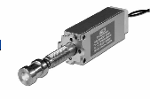
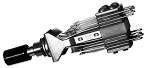
Blades are made from thin pieces of metal which are approximately 1/8" to 1/4" wide. The actual thickness varies depending upon how much current is being switched by the device. A thicker blade can handle more current than a thin one. Entech uses five different thicknesses: .031", .025", .020", and .012".
The blade length and whether or not it is bent (FORMED) depends on its function within the stack or "PILEUP". These are discussed in depth below. In the figure below, one can see the stack of contacts above and below the frame in the side view. The two longest blades are always in contact with the cam, which is how the circuit responds to the movement of the knob. Just below the top blade is a shorter "BUSHING BLADE" that is always in insulated contact with the cam lever blade. When the cam pushes up the lower blade, it also pushes up the upper blade at the same time. A contact blade is even shorter and the "BLADE STOP" piece is the shortest of all the parts in the stack.
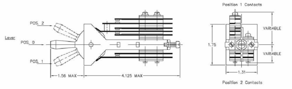
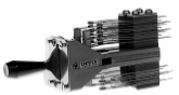
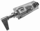
Lever Function
When the cam lever is pushed up to "Position #2", contacts on the bottom side of the switch are mechanically activated. Pushing the lever down activates the contacts on the top half of the switch. Note that on the above switch there are four PILEUPS, on in each of the four quadrants in the above figure. Quadrants divide the switch into four equal parts. The pileups may have different blades in each quadrant. Also, switches may be built with pileups only in one of the four quadrants, all of the four quadrants, or any combination in-between.
When the cam lever is pushed up to "Position #2", contacts on the bottom side of the switch are mechanically activated. Pushing the lever down activates the contacts on the top half of the switch. Note that on the above switch there are four PILEUPS, on in each of the four quadrants in the above figure. Quadrants divide the switch into four equal parts. The pileups may have different blades in each quadrant. Also, switches may be built with pileups only in one of the four quadrants, all of the four quadrants, or any combination in-between.
Lever Design
The lever design shown in the above figure is available in three versions; "LOCKING", "NON-LOCKING", and "NO-THROW". These terms describe the action of the lever when moved. "LOCKING" means the lever that springs back to its original position when the moving force is removed. "NON-LOCKING" describes a lever that springs back to its original position when the moving force is removed. "NO-THROW" means lever movement to that position is BLOCKED and is not mechanically permitted.
The lever design shown in the above figure is available in three versions; "LOCKING", "NON-LOCKING", and "NO-THROW". These terms describe the action of the lever when moved. "LOCKING" means the lever that springs back to its original position when the moving force is removed. "NON-LOCKING" describes a lever that springs back to its original position when the moving force is removed. "NO-THROW" means lever movement to that position is BLOCKED and is not mechanically permitted.


Entech Controls Corporation 8 Tower Circle West Ormond Beach, FL 32174
Tel: (386) 672-7335 Fax: (386) 672-7233 entechsales@cfl.rr.com
Tel: (386) 672-7335 Fax: (386) 672-7233 entechsales@cfl.rr.com
Last Revised February 14, 2012
2013 Entech Controls Corporation